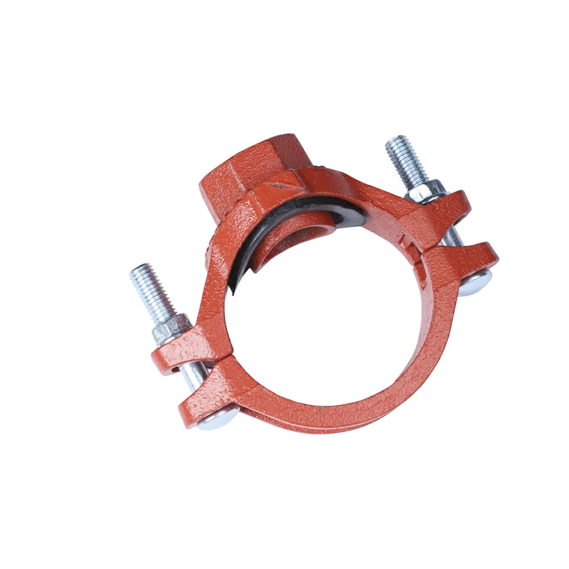
Calculating the torque required to operate a grooved mechanical tee involves considering several factors, including the size and material of the tee, the type of gasket used, the number and size of bolts, and the required bolt preload.

Here’s a general procedure for calculating the torque:

  1. Determine the Bolt Preload Requirement: The bolt preload is the tension applied to the bolts to ensure a proper seal between the gasket and the mating surfaces of the tee. The preload is typically specified by the manufacturer and depends on factors such as gasket material, bolt size, and operating conditions. Refer to the manufacturer’s specifications or industry standards (e.g., AWWA, ASTM) to determine the required bolt preload for the specific application.
  2. Calculate the Required Bolt Tension: Use the bolt preload requirement to calculate the required bolt tension. Bolt tension is calculated using the formula:𝑇=𝐾×𝐹T=KΓ—FWhere:
    • 𝑇T is the bolt tension (force applied by each bolt).
    • 𝐾K is the coefficient of friction between the bolt threads and the nut (typically provided by the manufacturer).
    • 𝐹F is the bolt preload or axial force required to compress the gasket and achieve a proper seal.
  3. Determine the Bolt Torque: Once the required bolt tension is known, the bolt torque can be calculated using the formula:π‘‡π‘ž=𝑇×𝐷𝐾×𝐹𝑑Tq​=KΓ—Fd​TΓ—D​Where:
    • π‘‡π‘žTq​ is the bolt torque.
    • 𝑇T is the bolt tension calculated in step 2.
    • 𝐷D is the nominal diameter of the bolt (measured across the threads).
    • 𝐹𝑑Fd​ is the thread friction factor (typically provided by the manufacturer).
  4. Calculate the Total Torque: To determine the total torque required to operate the grooved mechanical tee, multiply the bolt torque calculated in step 3 by the number of bolts used in the tee assembly.π‘‡π‘œπ‘‘π‘Žπ‘™Β π‘‡π‘œπ‘Ÿπ‘žπ‘’π‘’=π‘‡π‘žΓ—π‘TotalTorque=Tq​×NWhere:
    • 𝑁N is the number of bolts in the tee assembly.
  5. Verify and Adjust: Verify the calculated torque against the manufacturer’s recommendations and adjust as necessary based on factors such as gasket material, bolt size, surface condition, and operating conditions. Ensure that the torque is within the allowable range specified by the manufacturer to avoid over-tightening or under-tightening the bolts.

It’s essential to follow the manufacturer’s installation instructions and torque specifications when operating a grooved mechanical tee to ensure proper assembly, sealing, and performance. Additionally, consider consulting with a qualified engineer or technician familiar with grooved piping systems for guidance on torque calculation and installation procedures specific to your application.

The flash and fire point test is an important procedure made use of to figure out the flammability and safety and security of petroleum items, such as gas, oils, and lubes. The test gives beneficial information concerning the temperature level at which a compound can create combustible vapors and spark, which is crucial for making certain secure handling, storage, and transport of these items.

Here’s the importance of the flash and fire point test:

Safety and security Examination: The flash and fire point test assists examine the fire and explosion threats related to oil items. Recognizing the temperatures at which these items can spark offers useful info for carrying out precaution to prevent mishaps and secure workers, equipment, and facilities.

Governing Conformity: Several regulatory agencies, standards companies, and industry specs need flash and fire factor testing for petroleum items to ensure conformity with safety laws and requirements. Meeting these requirements is necessary for item qualification, regulatory authorization, and lawful conformity.

Quality Control: Flash and discharge point testing are integral parts of quality control treatments for oil items. Producers utilize these tests to confirm item uniformity, top quality, and performance, guaranteeing that items satisfy defined security and efficiency criteria prior to they are launched to the market.

Product Advancement: Blink and terminate point data are beneficial for product development and formulation. By understanding the flammability features of various petroleum items, manufacturers can maximize item formulations, enhance safety features, and improve performance to satisfy certain application demands and customer requirements.

Transportation and Storage: Blink and terminate point information is essential for the secure transportation and storage space of petroleum products. Knowing the temperature levels at which these products can fire up assists determine proper storage conditions, managing procedures, and safety and security preventative measures to prevent accidents, spills, leaks, or fires during storage space, loading, discharging, and transport.

Danger Assessment: Blink and fire factor data are utilized in risk analyses and risk analyses to assess the possible dangers associated with the handling, storage space, and use of oil items. This information enables companies to identify and mitigate potential hazards, establish emergency situation reaction plans, and implement preventive measures to minimize the chance and seriousness of crashes or incidents.

Generally, the flash and fire point test plays a crucial role in ensuring the safety and security, high quality, and regulative conformity of petroleum products. By providing vital details regarding flammability features, these examinations aid safeguard personnel, centers, and the environment from the dangers related to handling, storing, and utilizing these items.

Metal seal gate valves, like other types of valves, can be affected by freezing temperatures if proper precautions are not taken.

Here’s how metal seal gate valves handle freezing temperatures and what measures can be implemented to mitigate potential issues:

  1. Material Selection: Metal seal gate valves are typically made from materials such as cast iron, ductile iron, or stainless steel, which are generally resistant to the effects of freezing temperatures. These materials have a high tolerance for cold temperatures and are less prone to damage or failure due to freezing.
  2. Design Features: Metal seal gate valves are designed to withstand the mechanical forces exerted by freezing water. The robust construction and sealing mechanisms of these valves help prevent damage from ice formation and expansion within the valve body.
  3. Proper Installation: Proper installation of metal seal gate valves is essential to minimize the risk of freezing-related issues. Valves should be installed in a manner that allows for proper drainage to prevent water from pooling and freezing within the valve body.
  4. Insulation: In colder climates or environments prone to freezing temperatures, additional insulation may be applied to metal seal gate valves to protect them from the effects of freezing. Insulation materials such as foam jackets or heat tape can help maintain the temperature of the valve and prevent ice formation.
  5. Heat Tracing: Heat tracing systems can be installed along the exterior of metal seal gate valves to provide supplemental heat and prevent freezing. These systems use electric heating elements or circulating hot water to maintain the temperature of the valve above freezing.
  6. Winterization: In situations where metal seal gate valves are not in use during freezing conditions, they may be winterized to protect them from damage. This can involve draining the valve and associated piping to remove any residual water that could freeze and cause issues.
  7. Regular Maintenance: Regular maintenance of metal seal gate valves is important to ensure they remain in optimal condition and are less susceptible to freezing-related problems. Inspections should be conducted periodically to identify any signs of damage or wear that could compromise the valve’s integrity.

By implementing these measures, metal seal gate valves can effectively handle freezing temperatures and continue to operate reliably in cold environments. Proper installation, insulation, and maintenance are key to ensuring the longevity and performance of these valves in freezing conditions.

Operating firefighting foam equipment effectively requires specific training to ensure personnel understand how to use the equipment safely and efficiently.

Here’s an overview of the training typically required:

  1. Basic Firefighting Training: Before operating foam equipment, individuals should undergo basic firefighting training, which covers fire behavior, fire suppression techniques, and general firefighting safety procedures. This foundational knowledge provides a context for understanding how foam equipment fits into overall firefighting operations.
  2. Foam Equipment Familiarization: Training should include detailed instruction on the types of foam equipment used, including foam generators, foam proportioning systems, foam applicators, and associated tools. Personnel should become familiar with the components, functions, and operation of each type of equipment.
  3. Foam Types and Applications: Training should cover different types of firefighting foam (e.g., AFFF, AR-AFFF, protein-based, synthetic-based) and their respective applications. Personnel should understand when and how to use each type of foam effectively based on the type of fire and the materials involved.
  4. Foam Proportioning Systems: Personnel should receive training on foam proportioning systems, which are used to mix foam concentrate with water at the correct ratio. This training should cover how to set up, calibrate, and operate proportioning systems to achieve the desired foam concentration.
  5. Equipment Setup and Operation: Training should include hands-on practice in setting up foam equipment, including connecting hoses, China fire fighting Foam Equipment manufacturer adjusting flow rates, and activating foam application systems. Personnel should understand how to operate foam equipment safely and efficiently in various firefighting scenarios.
  6. Foam Application Techniques: Personnel should learn proper foam application techniques, including nozzle selection, application patterns, and coverage strategies. Training should emphasize achieving adequate foam coverage to smother and suppress fires effectively.
  7. Safety Procedures: Training should emphasize safety procedures specific to foam firefighting operations, including proper personal protective equipment (PPE) usage, foam concentrate handling procedures, and precautions for working near hazardous materials.
  8. Emergency Response Protocols: Personnel should be trained in emergency response protocols, including procedures for equipment malfunction, foam concentrate spills, and unexpected fire behavior. Training should include drills and simulations to practice response procedures in realistic scenarios.
  9. Regulatory Compliance: Training should cover relevant regulations, standards, and best practices for foam firefighting operations, including compliance with NFPA standards and local regulatory requirements.
  10. Continuing Education and Refresher Training: Ongoing training and refresher courses should be provided to ensure personnel maintain proficiency in operating foam equipment and stay updated on advances in foam firefighting technology and techniques.

By providing comprehensive training on foam equipment operation, fire departments and organizations can ensure that personnel are prepared to effectively and safely respond to fires involving flammable liquids, hazardous materials, and other situations where foam firefighting is required.

The accuracy of the aiming system of a fire monitor can vary depending on several factors, including the design of the monitor, the control mechanism, environmental conditions, and the skill of the operator.

Here are some considerations regarding the accuracy of a fire monitor’s aiming system:

  1. Design and Construction: Fire monitors are typically designed with precision aiming mechanisms that allow for accurate control of the direction and angle of the water stream. High-quality monitors incorporate robust construction and precise engineering to ensure consistent and reliable aiming performance.
  2. Control Mechanism: The control mechanism used to adjust the direction and angle of the fire monitor plays a significant role in its accuracy. Remote-controlled monitors may use joysticks, control panels, or digital interfaces that provide precise control over aiming adjustments.
  3. Sensitivity and Responsiveness: Aiming systems should be sensitive and responsive to operator input, China Fire Monitor manufacturer and supplier allowing for fine adjustments to be made quickly and accurately. Smooth and intuitive control mechanisms enhance the accuracy of aiming adjustments.
  4. Environmental Conditions: Environmental factors such as wind, water pressure, and vibrations can affect the accuracy of a fire monitor’s aiming system. Operators may need to compensate for these factors to maintain accurate targeting of the water stream.
  5. Training and Experience: The skill and experience of the operator also influence the accuracy of the fire monitor’s aiming system. Proper training and familiarization with the equipment enable operators to effectively control the monitor and achieve precise targeting of the water stream.
  6. Feedback Systems: Some fire monitors incorporate feedback systems that provide operators with real-time information about the monitor’s position and orientation. This feedback helps operators make accurate aiming adjustments and maintain optimal firefighting effectiveness.

Overall, while fire monitors are designed to provide accurate aiming capabilities, achieving precise targeting depends on various factors, including the design of the monitor, the control mechanism, environmental conditions, and operator skill. Proper training, regular maintenance, and effective communication between operators and other firefighting personnel are essential for maximizing the accuracy and effectiveness of a fire monitor’s aiming system.

Reflective road studs play a crucial role in assisting drivers in identifying toll booths or rest areas by providing clear visual cues and delineating the roadway.

Here’s how they contribute to this:

  1. Lane Guidance: Reflective road studs are often used to mark lanes leading to toll booths or rest areas, guiding drivers along the correct path. By positioning reflective studs in a specific pattern or sequence, road authorities can clearly delineate lanes dedicated to toll collection or access to rest areas.
  2. Lane Differentiation: Reflective road studs help differentiate lanes that lead to toll booths or rest areas from other lanes on the roadway. Different colors or configurations of reflective studs may be used to designate specific lanes for toll collection, vehicle parking, or rest area access, making it easier for drivers to identify the intended route.
  3. Visibility at Night: The reflective properties of road studs ensure their visibility at night or in low-light conditions, enhancing their effectiveness in guiding drivers to toll booths or rest areas. This visibility is particularly important when signage or other roadway markings may be less visible due to reduced visibility.
  4. Consistency with Road Markings: Reflective road studs are often used in conjunction with other roadway markings, such as lane lines and directional arrows, to provide consistent guidance to drivers. By aligning with these markings, reflective studs reinforce important navigational information and improve overall driver comprehension of the roadway layout.
  5. Positioning Near Entry/Exit Points: Reflective road studs may be strategically positioned near entry and exit points of toll booths or rest areas to provide additional visual cues to drivers. These studs serve as markers indicating the location of access points, reflective road studs helping drivers navigate safely to their destination.
  6. Integration with Signage: Reflective road studs may be integrated with signage indicating the presence of toll booths or rest areas. By positioning road studs in proximity to these signs, their visibility is further enhanced, making it easier for drivers to identify and locate toll booths or rest areas, especially at night.
  7. Distance Markers: In some cases, reflective road studs may be used as distance markers leading up to toll booths or rest areas, indicating the remaining distance to these destinations. By providing advance warning to drivers, these markers help ensure smooth and safe navigation to toll booths or rest areas along the roadway.

Overall, reflective road studs play a vital role in assisting drivers in identifying toll booths or rest areas by providing clear visual guidance, enhancing visibility at night, reinforcing roadway markings, and integrating with signage and distance markers. Their strategic placement and consistent use contribute to safer and more efficient navigation for drivers on the road.

Roller barriers, while primarily designed as safety features to mitigate the severity of collisions, can indirectly assist in identifying emergency refuge areas along roadways. Here’s how:

  1. Visual Contrast: Roller barriers often have a distinct appearance compared to other roadside features, such as guardrails or concrete barriers. Emergency refuge areas, typically designated by signage or markings, may be positioned adjacent to or between sections of roller barrier. The visual contrast between the roller barrier and the refuge area signage can help draw attention to the location of emergency refuge areas for drivers approaching them.
  2. Spacing and Positioning: Roller barriers are installed along roadways at specific intervals, typically based on safety considerations and engineering standards. Emergency refuge areas are strategically positioned along the roadway to provide safe locations for vehicles to stop in emergencies. Roller barriers may be spaced further apart or interrupted at these locations to accommodate the refuge areas, making them more noticeable to drivers.
  3. Signage Integration: Emergency refuge areas are often marked with signage indicating their purpose and availability for motorists. roller barrier Roller barriers can be integrated with this signage, either by mounting signs directly on the barriers or by positioning them nearby. The combination of roller barriers and refuge area signage creates a clear visual indication of the presence and location of emergency refuge areas for drivers.
  4. Roadside Markings: In addition to signage, emergency refuge areas may be delineated by road markings or pavement treatments. Roller barriers can be installed in a manner that aligns with these markings, providing a physical boundary that reinforces the designated area for drivers. The consistent alignment between roller barriers and roadside markings helps drivers identify and recognize emergency refuge areas more easily.
  5. Height and Visibility: Roller barriers are often designed to be highly visible to drivers, with reflective surfaces or bright colors to enhance visibility, particularly at night or in adverse weather conditions. By positioning roller barriers near emergency refuge areas, their height and visibility can help drivers identify these areas from a distance and make informed decisions about using them in emergencies.

While roller barriers themselves may not directly indicate the presence of emergency refuge areas, their strategic placement and integration with signage, markings, and roadside features can help drivers identify and recognize these areas along roadways, enhancing overall road safety and providing valuable options for motorists in emergencies.

How do rolling barriers contribute to the visibility of rolling exits in nighttime conditions?

Rolling barriers, also known as rolling guardrails or impact attenuators, can contribute to the visibility of rolling exits in nighttime conditions through several mechanisms:

  1. Reflective Surfaces: Many rolling barriers are equipped with reflective surfaces, such as reflective strips or panels, that enhance their visibility in low-light conditions. These reflective elements reflect light from vehicle headlights, making the rolling barriers more conspicuous to drivers approaching rolling exits at night.
  2. High-Visibility Colors: Rolling barriers are often painted in high-visibility colors, such as fluorescent yellow or orange, which stand out against the darker background of the roadway, particularly at night. These bright colors help draw attention to the presence of rolling exits and guide drivers toward them.
  3. Illumination: Some rolling exits may be equipped with lighting fixtures positioned along the rolling barriers to provide additional illumination. This lighting helps improve the visibility of rolling exits and the surrounding area, making them easier for drivers to identify and navigate, even in nighttime conditions.
  4. Strategic Placement: Rolling barriers are typically positioned along the edges of roadways, including near rolling exits, to provide protection and containment in the event of a collision. The strategic placement of rolling barriers ensures that they are located in close proximity to rolling exits, maximizing their visibility to drivers.
  5. Consistency with Roadway Markings: Rolling barriers are often installed in alignment with roadway markings, rolling barriers such as lane lines and edge lines, providing a continuous visual cue for drivers. This consistency helps drivers anticipate the location of rolling exits and navigate toward them with greater confidence, even in low-light conditions.
  6. Reflective Signage: Rolling exits may be accompanied by reflective signage indicating their presence and providing directional information to drivers. By positioning rolling barriers near these reflective signs, their visibility is further enhanced, helping drivers locate and access rolling exits more easily at night.
  7. Regular Maintenance: Ensuring that rolling barriers are clean, well-maintained, and free from obstructions is essential for maximizing their visibility, especially at night. Regular maintenance activities, such as cleaning reflective surfaces and replacing damaged or faded components, help ensure that rolling barriers remain highly visible to drivers in all lighting conditions.

By incorporating these visibility-enhancing features and practices, rolling barriers help improve the visibility of rolling exits in nighttime conditions, promoting safer navigation and reducing the risk of accidents at exit points along roadways.

Block making machines are designed to handle interruptions or disruptions during operation in several ways to minimize downtime and maintain productivity:

  1. Safety Features: Block making machines are equipped with safety features such as emergency stop buttons, safety guards, and sensors to detect anomalies or hazards. In the event of an interruption or disruption, operators can quickly activate the emergency stop mechanism to halt machine operation and address the issue safely.
  2. Fault Detection Systems: Many block making machines are equipped with fault detection systems that monitor machine performance in real-time. If a fault or malfunction is detected, the system can automatically pause operation, alert operators to the problem, and provide diagnostic information to facilitate troubleshooting and repairs.
  3. Automatic Reset Functions: Some block making machines feature automatic reset functions that enable the machine to resume operation after an interruption or disruption once the issue has been resolved. This helps minimize downtime and streamline the restart process, ensuring efficient operation and productivity.
  4. Manual Override Capability: Block making machines may include manual override capabilities that allow operators to bypass automated functions and manually control machine operation in the event of a disruption. block making machine for sale in usa Manual override features enable operators to troubleshoot problems, make adjustments, or perform maintenance tasks as needed to restore normal operation.
  5. Backup Power Systems: In facilities with unreliable power sources or frequent power outages, block making machines may be equipped with backup power systems such as generators or battery backups. These backup systems can provide temporary power supply during interruptions or disruptions, allowing machine operation to continue uninterrupted until primary power is restored.
  6. Remote Monitoring and Control: Some block making machines offer remote monitoring and control capabilities that enable operators to monitor machine performance, diagnose issues, and make adjustments from a remote location. Remote access allows operators to respond to interruptions or disruptions quickly, even if they are not physically present at the machine.
  7. Preventive Maintenance Programs: Implementing preventive maintenance programs can help reduce the likelihood of interruptions or disruptions during machine operation. Regular maintenance activities, such as lubrication, cleaning, and inspection, can help identify and address potential issues before they escalate into major problems, minimizing unplanned downtime and maximizing machine reliability.
  8. Operator Training and Support: Providing comprehensive training and support to machine operators can help them effectively manage interruptions or disruptions during operation. Well-trained operators are better equipped to troubleshoot problems, follow safety protocols, and implement contingency plans to minimize downtime and maintain productivity in the event of disruptions.

Overall, block making machines are designed with various features and strategies to handle interruptions or disruptions during operation, including safety features, fault detection systems, automatic reset functions, manual override capabilities, blocks machine price backup power systems, remote monitoring and control, preventive maintenance programs, and operator training and support. By implementing these measures, manufacturers can ensure efficient and reliable operation of block making machines and minimize the impact of interruptions on productivity and profitability.

How does a blocks machine minimize waste and maximize efficiency in brick production?

A blocks machine can minimize waste and maximize efficiency in brick production through several strategies and features:

  1. Optimized Material Usage: Blocks machines are designed to minimize material waste by efficiently utilizing raw materials such as concrete, cement, aggregates, and additives. Precise dosing and mixing mechanisms ensure that the correct proportions of materials are used, reducing overconsumption and minimizing waste.
  2. Customizable Production: Many blocks machines offer customizable production options, allowing manufacturers to produce bricks in various sizes, shapes, and designs according to specific project requirements or customer preferences. By tailoring production to meet exact specifications, manufacturers can minimize waste associated with excess or unused inventory.
  3. On-Demand Production: Blocks machines can facilitate on-demand production of bricks, allowing manufacturers to produce only the quantity needed for immediate use or customer orders. By avoiding overproduction and excess inventory buildup, on-demand production minimizes waste and maximizes efficiency in brick manufacturing.
  4. Quick Changeover Features: Blocks machines may incorporate quick changeover features that enable rapid transition between different brick sizes, shapes, or colors. By minimizing downtime associated with changeovers, manufacturers can optimize production efficiency and responsiveness to changing market demands, reducing waste and maximizing resource utilization.
  5. Recycling and Reuse of Waste Materials: Some blocks machines are capable of processing recycled or reclaimed materials, such as crushed concrete, construction waste, or industrial by-products, into bricks. By incorporating recycled materials into brick production, manufacturers can reduce waste disposal costs, conserve natural resources, and promote sustainability in manufacturing operations.
  6. Energy Efficiency: Blocks machines are designed to operate efficiently and consume minimal energy during production. Energy-efficient motors, cinder block maker automated controls, and optimized production processes help minimize energy consumption and reduce operating costs, maximizing efficiency and sustainability in brick manufacturing.
  7. Quality Control Mechanisms: Blocks machines incorporate quality control mechanisms to ensure consistent brick quality and performance. Automated monitoring systems, sensors, and inspection processes help detect defects or deviations from quality standards, allowing manufacturers to identify and address issues promptly to minimize waste and rework.
  8. Lean Manufacturing Principles: Many blocks machines are designed based on lean manufacturing principles, which emphasize continuous improvement, waste reduction, and efficiency optimization. By implementing lean practices such as value stream mapping, process optimization, and continuous monitoring, manufacturers can identify opportunities for waste reduction and efficiency improvement in brick production.

Overall, blocks machines can minimize waste and maximize efficiency in brick production by optimizing material usage, offering customizable production options, facilitating on-demand production, incorporating quick changeover features, recycling and reusing waste materials, ensuring energy efficiency, implementing quality control mechanisms, and adhering to lean manufacturing principles. By adopting these strategies and features, manufacturers can enhance sustainability, profitability, and competitiveness in the brick manufacturing industry.

A block maker machine can facilitate the recycling or reuse of waste materials in several ways:

  1. Material Compatibility: Many block maker machines are designed to process a wide range of raw materials, including recycled or reclaimed materials such as crushed concrete, construction waste, fly ash, slag, and industrial by-products. By accepting diverse input materials, block maker machines enable the recycling and reuse of waste materials that would otherwise be discarded or disposed of in landfills.
  2. Mixing and Blending: Block maker machines incorporate mixing and blending mechanisms that homogenize raw materials, ensuring uniform composition and quality in the finished blocks. By mixing recycled materials with traditional aggregates or binders, block maker machines can produce high-quality blocks that meet industry standards and performance requirements, thereby enhancing the viability of recycled material utilization in construction applications.
  3. Particle Size Reduction: Some block maker machines feature built-in crushers or pulverizers that reduce the size of bulky or irregularly shaped waste materials into smaller, uniform particles suitable for block production. By shredding or pulverizing waste materials, block maker machines facilitate the processing of diverse feedstocks and enhance the efficiency of material recycling and reuse efforts.
  4. Material Compaction: Block maker machines apply compression and compaction forces to raw materials, transforming them into compacted blocks with high structural integrity and strength. By compacting recycled materials into durable blocks, block maker machines enable the utilization of waste materials in load-bearing construction applications, such as retaining walls, pavements, and building foundations.
  5. Customization Options: Many block maker machines offer customization options for block design, size, shape, and composition, allowing operators to tailor block specifications to specific project requirements or material availability. block maker machine By accommodating variations in recycled material properties and characteristics, block maker machines enable the optimization of material utilization and resource efficiency in construction projects.
  6. Quality Assurance: Block maker machines incorporate quality control mechanisms, such as automated monitoring systems and standardized production processes, to ensure consistent block quality and performance. By adhering to strict quality standards and specifications, block maker machines enable the use of recycled materials in construction applications without compromising structural integrity, durability, or safety.
  7. Waste Reduction: By converting waste materials into value-added products, such as concrete blocks, pavers, or bricks, block maker machines help reduce the volume of waste sent to landfills and mitigate environmental impacts associated with waste disposal. By promoting material recycling and reuse, block maker machines contribute to sustainable waste management practices and resource conservation efforts.

Overall, block maker machines play a crucial role in facilitating the recycling or reuse of waste materials by processing diverse feedstocks, mixing and blending raw materials, reducing particle size, compacting materials into blocks, offering customization options, ensuring quality assurance, and reducing waste generation. By enabling the utilization of recycled materials in construction applications, block maker machines contribute to resource efficiency, environmental sustainability, and circular economy principles in the building and construction sector.

Solar road studs contribute to reducing light pollution and preserving the natural environment around roadways in several ways:

  1. Directed Illumination:
    • Solar road studs are designed to provide directed illumination, focusing light on the road surface rather than scattering it in all directions.
    • This targeted lighting minimizes the upward dispersion of light, reducing the impact on the night sky and surrounding areas.
  2. Low Intensity and Uniformity:
    • The intensity of the illumination from solar road studs is typically lower compared to traditional streetlights.
    • By maintaining low-intensity lighting, solar road studs help prevent excessive brightness and glare, contributing to a more uniform and controlled lighting environment.
  3. Dark Sky-Friendly Design:
    • Some solar road studs adhere to dark sky-friendly design principles, emphasizing the importance of minimizing light pollution.
    • These studs are designed to emit light only where it is needed, reducing the amount of stray light escaping into the night sky.
  4. Selective Wavelengths:
    • Solar road studs can be engineered to emit light within specific wavelength ranges, minimizing the impact on nocturnal wildlife and ecosystems.
    • By avoiding certain wavelengths associated with disruption to natural processes, solar road studs contribute to environmental preservation.
  5. On-Demand and Adaptive Lighting:
    • Many solar road studs are equipped with on-demand or adaptive lighting features.
    • These features allow the studs to activate or solar road studs adjust their brightness levels based on real-time conditions, ensuring that lighting is only utilized when necessary.
  6. Energy-Efficiency and Off-Grid Operation:
    • Solar road studs operate off-grid, relying on solar energy stored in batteries during daylight hours.
    • This off-grid operation reduces the need for traditional electric lighting, decreasing overall energy consumption and mitigating environmental impact.
  7. Reduced Light Trespass:
    • Solar road studs contribute to reducing light trespass by confining illumination to the roadway and immediate surroundings.
    • This minimizes the spread of light into areas where it is not needed or desired, preserving the darkness of the surrounding environment.
  8. Preservation of Natural Circadian Rhythms:
    • By providing localized and controlled illumination, solar road studs contribute to preserving natural circadian rhythms for both humans and wildlife.
    • Excessive artificial lighting at night can disrupt the natural behavior and health of nocturnal species.
  9. Compliance with Lighting Regulations:
    • Solar road studs are designed to comply with lighting regulations and standards aimed at minimizing light pollution.
    • Adherence to these guidelines ensures that the environmental impact of roadway lighting is within acceptable limits.
  10. Community and Stakeholder Engagement:
    • In some cases, solar road studs are implemented as part of community-driven initiatives to reduce light pollution.
    • Engaging with local communities and stakeholders helps ensure that lighting solutions align with environmental conservation goals.

By incorporating these design features and principles, solar road studs contribute to creating a more sustainable and environmentally friendly lighting solution for roadways, promoting responsible illumination practices that prioritize the preservation of the natural nighttime environment.